Posts Tagged Security Technology

The Security Risk of Wireless Alarm Systems: Lessons from Recent Detroit Burglaries


In recent years, technological advancements have brought about significant improvements in home security systems, making it easier than ever to protect our homes and loved ones. Wireless alarm systems, in particular, have gained popularity for their convenience and accessibility. However, as the saying goes, “with great power comes great responsibility.” Recent high-end burglaries in Detroit, specifically in Oakland County, have highlighted the security risks associated with wireless alarm systems. In this article, we will delve into these security concerns and explore the lessons we can learn from these unfortunate incidents.

The Detroit Burglaries: A Wake-Up Call

Since September of 2023, the city of Detroit has been rocked by a series of high-end burglaries that sent shockwaves through the community. Millions of dollars’ worth of valuables were stolen from homes across Oakland County, leaving homeowners shocked and law enforcement agencies scrambling to find answers. Two articles, one from ClickOnDetroit 1 and the other from Fox2Detroit 2, shed light on the situation, revealing that these heists were linked to a sophisticated Chilean crime ring.

While the details of these burglaries are indeed alarming, what’s equally unsettling is the fact that several of the targeted homes had wireless alarm systems in place. This raises a critical question: are these systems providing the level of security homeowners believe they are?

The Vulnerabilities of Wireless Alarm Systems

Wireless alarm systems have gained popularity because of their ease of installation, convenience, and scalability. However, they are not without their vulnerabilities, as the recent Detroit burglaries have shown. Here are some key security risks associated with wireless alarm systems:

  1. Signal Jamming: Wireless alarm systems rely on radio frequency signals to communicate between sensors and the control panel. Sophisticated burglars can use signal jammers to disrupt these signals, rendering the alarms useless.  These jammers are inexpensive and readily available, with a short learning curve on how to use them.  In some cases, just broadcasting with a small handheld radio on a specific frequency can disable a wireless door or window sensor.
  2. Hacking: In an era of interconnected devices, wireless alarm systems can be vulnerable to hacking attempts. Cybercriminals can gain access to your system and disarm it remotely, leaving your home exposed.
  3. Device Vulnerabilities: The devices themselves, such as door/window sensors and motion detectors, can be physically tampered with or disabled, making it easier for burglars to breach your home undetected.
  4. Limited Range: Wireless alarm systems typically have a limited range, making it essential to position sensors and repeaters strategically. If not done correctly, it can create blind spots that burglars can exploit.
  5. False Alarms: Wireless alarm systems are also prone to false alarms, which can lead to complacency on the part of homeowners or law enforcement agencies, potentially jeopardizing your home’s security.

Lessons Learned and Steps to Enhance Security

The recent Detroit burglaries serve as a stark reminder that even the most advanced security systems have their limitations. However, this doesn’t mean you should abandon wireless alarm systems altogether. Instead, consider the following steps to enhance your home’s security:

  1. Professional Installation: Opt for professional installation to ensure your wireless alarm system is set up correctly and securely.  Where possible, have sensors connected via hard wire, not wireless.  It may be more expensive initially, but is immune to signal jamming and the sensors don’t need battery replacements.
  2. Encryption: Choose a system with robust encryption to protect against hacking attempts.  Minimum encryption should be AES128 or better.
  3. Backup Power: Invest in a backup power supply to keep your system operational during power outages.  Backup power should last a minimum of 48-hours.
  4. Regular Updates: Keep your system’s firmware and software up to date to patch vulnerabilities.
  5. Supplement with Physical Security: Enhance your system with physical security measures like sturdy locks, reinforced doors, and security cameras.  Recorded video should be local to the camera (SD card) and a reliable video recorder on premises and/or in the cloud.
  6. Monitoring Services: Consider subscribing to a professional monitoring service that can alert authorities in case of an intrusion.  This is also beneficial for things like fire alarm monitoring, where they central station can dispatch the Fire Department to your house even if you’re not home.

Conclusion

Wireless alarm systems can be a valuable addition to your home security arsenal when used correctly and in conjunction with other security measures. However, it’s essential to be aware of their vulnerabilities and take steps to mitigate the risks. The recent high-end burglaries in Detroit remind us that staying informed and proactive about our home security is the key to protecting our homes and loved ones in an increasingly connected world.

As part of our services, Protective Resources performs dozens of Risk Assessments every year, sometimes for high-end executive residences of Fortune 500 corporations and other entities.    Many of these systems utilize wireless sensors or wireless internet connections for signaling or alarm notification.  While this is convenient, it opens up a potential attack surface for gaining entry to the premises.

References:

  1. “Millions of Dollars Lost in High-End Burglaries Across Oakland County” – ClickOnDetroit
  2. “High-End Michigan Burglaries Tied to Chilean Crime Ring Prompts Police Task Force” – Fox2Detroit

Posted in: Security Technology, Vulnerability Analysis

Leave a Comment (0) →

NEC and Conduit Fills for Communications and Security Cabling

A question that comes up frequently for us when working on security projects with high density device counts is conduit fill.   That National Electrical Code typically wants to limit conduit fill to less than 40% of the capacity for cables in the raceway.  This is based upon the dimensions of the conductors and the potential for “jamming” or stressing the cable and potential thermal issues that could lead to electrical fires.  This is referenced to apply to power cabling for AC power conductors.

We all know (or should know) that metallic low voltage communications cabling (e.g. CAT6 network, dry contact devices, card readers, etc) can’t be run in the same conduit as AC power cabling, so what is the limitation for conduit fill for low voltage security cabling?

Whenever you are in doubt, you should always consult with the AHJ, but in reality the NEC basically doesn’t care and it will likely never be inspected.  The manufacturers of these cables may have some recommendations on maximum fill ratings to reduce the pulling tension to minimize stretching or damaging the cable, however.  There are other factors in play of course: cable type, conduit type, distance, number of bends, and pulling lubricant used.

In short, be conservative with conduit fill for long runs of delicate small gauge multi-conductor cables like 22AWG TSP or CAT6A that could be damaged.   But for vertical cores between floors that are typically very short runs, you can probably fill to 80% without any significant risk, as long as the cable is properly supported and there is sufficient room remaining to properly apply intumescent firestop sealant.

Posted in: Access Control, Security Consulting

Leave a Comment (0) →

HID Signo Reader Shortage

As most people in the security industry know by now, Motorola HID has been having supply chain issues for months now for readers.  As a temporary solution, they are offering a new product line, “Signo Priority” readers, which lack the 125Khz Proximity function.

Signo Priority Features
 
– Same lifetime warranty as the traditional Signo readers
– Current lead time is 7 days (Sept 2022)
– Configured by profiles: Standard, Smart, Seos and Custom
– IP65 certified
– Automatic self-calibration when nearby metal surfaces are detected
– Factory equipped with Bluetooth (BLE Smarts) and NFC
 
Differences from traditional Signo Readers
 
– Lead time > 180 days (Sept 2022)
– Signo Priority will not read 125 Khz Proximity
 
If 125Khz reading is not needed, only 13.56 Mhz,  please consider the Signo Priority Reader X0NKS-T0-000000 as a substitute for the Signo Traditional X0NKS-00-000000 readers.


Posted in: Company News

Leave a Comment (0) →

The use of shielded category Ethernet cable for IP Video

It comes up from time to time from customers and vendors when and where to use shielded category twisted pair cable for Ethernet.   Most vendors hate it.  It’s hard to terminate, doesn’t flex well and nobody ever seems to agree on how it should be grounded.    For the most part, it wasn’t much of a problem for CAT3 or even CAT5 cable.  But with higher and higher bandwidth (and thus frequency) demands on the cable, using CAT6A cable in certain environments for network applications becomes important.   And while there’s a decent argument for why you may not need CAT6A cable for IP video (see this article for more information), many of our clients are using it as a corporate standard, regardless of the application.

Although CAT6 cables have improved the cable twist to handle gigabit Ethernet and reject noise, this by itself is not enough for environments that have high electromagnetic interference (EMI).  What is EMI?  Think of EMI as gremlins that are trying to attack the signal of your network cable.  EMI is generated as electromagnetic waves in the radio frequency (RF) spectrum, and can come from many sources.  The most logical is an RF transmitter, like a radio station tower or even HAM radio antenna; but other sources can be harder to spot, such as a nearby computer, high voltage power lines, a leaky transformer, or fluorescent light fixture that’s going bad.   Running network cables in your ceiling or plenum space could potentially put these cables near those kinds of sources, and thus introducing the gremlins to degrade or even interrupt communications over the Ethernet network cable.   Since Ethernet is a collision based network strategy, this usually looks like a slow connection, as the network repeatedly keeps re-transmitting packets that were found to be in error.  Result, poor network performance and potentially bad video.

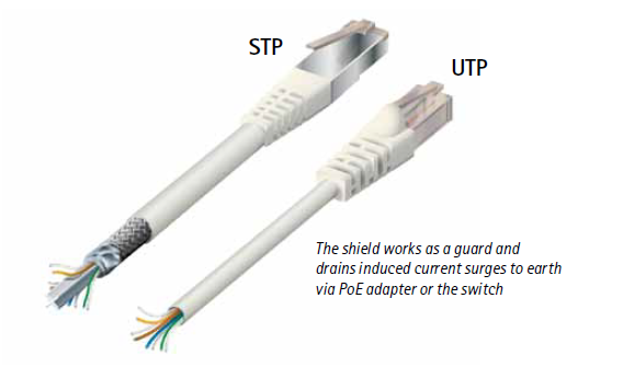
Most people are familiar with UTP cable (Unshielded Twisted Pair), versus STP (Shielded Twisted Pair), and UTP is commonly used in CAT5e cabling that is predominant for gigabit Ethernet networking in most commercial and residential applications.  STP cables have an additional metallic braid that forms a sort of shield (google “Faraday shield” for how it works) around the conductors, and reduces the amount of interference that can be injected into the cable.   Still, both types of conductors (STP and UTP) have one thing in common, the twisted pair, that by itself reduces interference by its inherent design.

Photo courtesy of Axis Communications.

The drawback of STP cables is that they increase the total cost of the installation. STP cables are more expensive due to the shielding (and usually are higher quality), which is an additional material that goes into every foot of the cable.  The shielding also makes the cable heavier and stiffer. Thus, it is more difficult to handle during installation (pulling cable over long distances through a conduit is hard enough with flexible cable).

While most installations can be done effectively using UTP cable, we recommend using STP cable for high EMI environments like manufacturing, laboratory, or research facilities where other high energy or RF generating devices may be in use.  Also, if you’re forced to run category cable in a cable tray that’s shared with power conductors (low or medium voltage), use STP cable even though the cable tray is separated and may have it’s own shielding for the power conductors.   It is also highly recommended to use an STP cable where the camera is installed outdoors or where the network cable is routed outdoors.

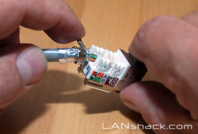
Oh, and what to do with that drain wire?  Our suggestion is to use some of the pre-fabricated shielded keystone jacks like this one.

Posted in: IP Video

Leave a Comment (0) →

Products That Don’t Exist, But Should

While working with a client for a high end residence, he brought up the video door bell gadgets that are all over the internet and in every Lowes or Home Depot. The objective was to have a decorative camera that would recognize video motion and record video and sound for visitors at the doorstep.

There are quite a few of these products available on the market, and for the general consumer they are probably a good fit.   But for our client base, a high end residence will typically have an integrated security and access control system, including video cameras.   Products like Ring and SkyBell must be used with a contract service that stores the video in the cloud, and are typically accessed and viewed via a smartphone app and are proprietary in nature.   This means they don’t support standards like RTSP or ONVIF which would allow off the shelf network video recorders (NVR) to record the video on-site or remotely as part of a comprehensive monitoring service.

To make things worse, these cameras typically operate over WiFi, and do not have any kind of battery backup.   Unreliable wireless communications and unreliable power don’t make for good security.   But at the same time we don’t want to add some industrial looking door bell to the client’s residence.   So what residential products like this are available currently that we can connect to our own NVR?  Nothing.   Really…. nada, zip, zilch.   There are currently no low profile, decorative products commercially available that will support a hardwired video connection and operate as a standard doorbell camera.

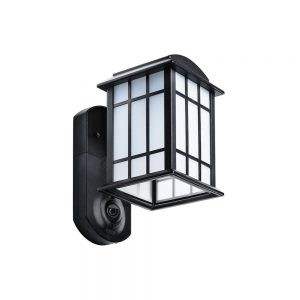
Another option was a product with a security camera integrated into the porch light.  Kuna makes some great looking products that would fit most any residential style and decor.  Kuna Maximus Light w/Camera But again, these products lock you into a monthly cloud service contract with proprietary protocols that are not available to 3rd party NVRs.  The Kuna Maximus product almost fits the bill too, providing good looks with security lighting, 720P video and two-way voice communications, but it still requires WiFi and is proprietary.

Someone Please Build This:

Here’s a product idea for high end residential and ornate commercial environments that want additional security.   Take a product like the Kuna Maximus where you have a decorative security light with a built in camera, but instead make it with the following features:

  • Motion Triggered Lighting (two-level lighting for soft accent lighting and full power security lighting when motion is detected).
  • 2 Megapixel IP Camera with Night Vision, H.264 video codec.
  • Two way audio communications with built-in microphone and speaker.
  • Support for HTTP, ONVIF, RTSP, FTP, SMTP, DHCP, DDNS, and SNMP protocols.
  • 10/100 Ethernet via built in powerline adapter, plus 802.11ac Dual Band 2.4G/5G Wireless support

So here’s the thinking behind this.  Almost every residence has a porch light at the front door.  This device would replace the existing wall mounted porch light, using the exact same 2-wire 12o VAC power that already exists.  It operates as any other motion security light, either “off until motion sensed”, or “1/2 brightness until motion sensed and then full brightness”.  It takes any standard Edison bulb.   The good part comes in where we add the camera that can use WiFi (if you must) or the built-in powerline Ethernet interface, allowing you to connect it to your own home network using a powerline module plugged into the wall near your router and then via CAT5 to your router.   From there it can behave as any other network camera on your NVR, or it can operate standalone with video motion detection and send emails when triggered, or upload via FTP to a web server, or whatever.  The powerline Ethernet adapters allow us to avoid WiFi where we can, and use the existing power wiring, eliminating the need for additional CAT5 cabling to the light.  If video is centrally monitored, the remote operator could communicate via IP audio to the person in front of the camera using a video management server.

This product should already exist, and quite frankly I can’t believe it doesn’t.  It would probably cost less than $300 retail, and I’d not only be using them on every executive residence that I was responsible for, I’d have one on my own home too.   And if you really want to have some contract service to store video in the cloud, fine… just don’t make it the only option.


Posted in: Reviews

Leave a Comment (0) →

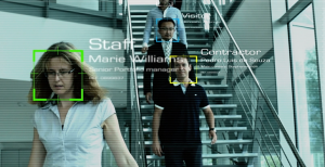
Facial Recognition for Access Control?

Several years ago,  I worked on a project prototype for a major group of sea ports that had an interest to use the state’s drivers license image database for facial recognition/verification of TWIC applicants and the eventual use for identity verification for critical card access points.  The main focus of the project was to ensure that the person applying for the TWIC card was indeed who they claimed to be, and not an imposter.   Neither the CCTV system nor the card access system had the built in software to do this, much less do it together, so we had to write the interface and the software to manage it.  It worked, but not as well as we would have liked.   We used a GPL’d algorithm for the facial recognition, which while good, would have some false positives and false negatives from time to time.   Ultimately to me, it served as a proof of concept.  It did work, and could be made as a serviceable monitoring and investigation tool for security.  (Later we used that same GPL software to create a tool that would scrounge through the card access database and crop the cardholder photos to a uniform size.  THAT worked really well.)

Years later, as far as I know there is still not an off-the-shelf system that provides a true facial recognition monitoring capability for access control violations.  This seems like something very straightforward to do, and as most companies or government branches have an actively maintained photo database of their cardholder personnel, and most often have video cameras monitoring locations where access control is used.

The biggest limitation we found was the quality of the CCTV images against the badge database photos.   Both were of rather poor quality, but if we used the software as just a pre-filtering tool for security operators, the margins of error were more tolerable.  The idea was to still have a security guard doing the verification, but not for every photo, just the ones the software couldn’t handle well.

Cardholder with back to camera.

Poor camera angle doesn’t allow for good facial recognition

With Megapixel IP cameras replacing low resolution analog cameras, the probability improves of having a photo with an acceptable number of unique data points to match against an image database with a high degree of confidence.  This means more information data points to compare, and fewer false positives and negatives.   There are still other considerations such as angle of view, proper lensing, lighting, face concealment/alteration issues, and image database accuracy.  And you must have most, if not all of these considerations to have a usable image.  As shown here, even if you have good lighting and resolution, if you don’t have a good angle and lensing, you will not have a usable image for facial recognition of the cardholder.

Currently, there are about a dozen corporations world wide that offer some type of facial recognition software.   Many of their larger customers are government agencies or the financial industry.  It is used in some border crossings, passport identification, and high profile monuments.   The FBI may be the most famous consumer of this technology, but it is not used in a widespread fashion as far as I know.  Naturally, this isn’t something that is widely advertised by these agencies.

Still, as such a highly technically savvy country as the USA supposedly is, I’ve often wondered why we don’t have facial recognition with a national database at all critical locations like border crossings, airports, bus stations, train stations, embassies, and hospitals.  I realize there’s a modest invasion of privacy, and nobody likes the thought of having “big brother” monitor your whereabouts, especially putting your name to your face in a specific location and time.   It’s kind of creepy.  But the other side of the coin is that if we maintain a central photographic database of active criminals and terrorists (which we do), then having feeds from certain cameras in certain high traffic locations might allow us to not only apprehend said criminals/terrorists in a timely manner, but even allow us to gain intelligence regarding their commuting patterns, associations, and personal habits.  This is beneficial information that can reduce crime and terrorism.

Keep in mind, the government already has a very large database of photos, probably including you, even if you don’t have a mug shot in the NCIC.  Facebook, Twitter, Instagram, LinkedIn, are all repositories available that most likely link your face with your name.   The FBI has said that by 2015, it plans to have 52 million photos in its NGI facial recognition database.   The FBI will include non-criminal information as well as criminal.  Where’d they get those?!    So, you may already be in the database, and maybe me too.  Obviously, some people will object to this idea, some even quite profusely.  But the genie is already out of the bottle.  Getting him stuffed back in is going to be difficult, if not impossible.

So the natural progression on this “big brother” concern just may be to license the database.   For a fee, allow vetted customers to have access to the database via an API to use this centralized database for government and limited private commercial purposes.  Want to know if your daughter or son is in the NGI database?  Maybe there’s a background check service company that can tell you.   But for financial institutions, or the port authority I mentioned in the beginning of this article, it would be a boon of intelligence data.   Not only would they have their own employees and contractors in their own database, they could also have access to a national database of “persons of interest” that could assist them in determining if a potential applicant is a criminal, or maybe even just a high risk.  That has the simultaneous possibility of reducing their own risks, and providing timely information to Homeland Security about a potential threats whereabouts and possible intentions.

Facial recognition of employees at work

Facial recognition in the workplace.

I think the future of this technology is already headed in this direction, and there may already be entities that are doing exactly what I’ve described, but I believe the technology will become more pervasive as some of the technological (and sociological) barriers are broken down.

Posted in: Access Control, Company News, Security Technology

Leave a Comment (0) →

Digital Video Forensics: Analog and IP Video Cameras

While time-lapse video recorders (TLR) using videocassettes remain in use in many smaller video surveillance systems, digital video recorders (DVR) and network video recorders (NVR) continue to be the preferred choice for larger and more complex systems. The video cameras that provide the images to these recording systems may be either analog or IP (internet protocol). For TLRs, analog cameras are almost invariably required, though it is technically possible to use IP cameras in a TLR system. For DVRs and NVRs, either analog or IP cameras, or a mixture of the two types, may be used. For the purpose of video forensics, knowing the type of camera that originally captured the video is critical to an understanding of several important aspects of the video material to be examined.

In North America, analog video cameras are almost certain to be compliant with the NTSC video system. (In other parts of the world, cameras may comply with PAL, SECAM, or other video system standards, which differ from NTSC in many crucial aspects. For the purpose of this discussion, we shall limit ourselves to the NTSC system.) The NTSC (National Television System Committee) standards for video systems were developed primarily to ensure the compatibility of broadcast television signals with consumer television sets.  The first standard was published in 1941, with subsequent revisions to accommodate advances such as color TV, and all of the standards are readily available from many sources for reference purposes.  The NTSC system standard is perhaps most important because it describes the way in which a video image is created on the “old-fashioned” CRT (cathode ray tube) television sets we used for well over 50 years. It should come as no surprise that analog video surveillance cameras of that period were designed and manufactured to provide a video picture that would display in an identical manner on video monitors using CRTs. Therefore, we can safely assume that an analog NTSC camera produces a signal that complies with the relevant sections of the NTSC standards.

Why is it important for a video forensics analyst to know if video material originated from an NTSC camera? Regardless of the method used to transmit and record the video images, the use of an analog NTSC camera places certain limitations and restrictions on the original video source and, consequently, on the recorded video images. We are frequently presented with digital video files that are known to have originated from an NTSC camera and, in many cases, can point to attributes of the video images that are inconsistent with an NTSC source. In some cases, there are anomalies that can be readily explained in no other way. In the following paragraphs, we will discuss a few of the most relevant features of the NTSC video system and the analog video cameras that employ it.

First, the aspect ratio of an NTSC video image is 1.33, or 4 units (wide) by 3 units (high). This aspect ratio is specified by the NTSC standards, but may vary slightly from system to system through minor variations in CRT scanning or other equipment variations. However, a DVR that produces a video file that is 720 pixels (wide) by 480 pixels (high) from an analog NTSC camera is either substantially distorting the image or cutting off portions of the image when recording since the aspect ratio of the digital video is 1.5 and definitely not 1.33. This is a common problem and once that we see in many cases.

Second, the standard frame rate for NTSC video is 29.97 frames per second. A new frame (complete image) is presented from the camera to the recorder every 33.4 milliseconds on a continuous basis. The consequences of this fixed, predictable frame rate can make a dramatic difference if the purpose of the analysis is to ascertain the exact time interval between any two frames in the digital video material. Since accurate and reliable time intervals are critical to establishing such basic data as the velocity of vehicles or other moving objects shown in the video, we are often asked to render an opinion on this specific aspect of the material. We will discuss this topic in more detail in a subsequent post. Ironically, “old-fashioned” videocassette recorders are often much better at providing accurate and reliable time interval measurements, as they were originally designed to record and play back video at precisely the same rate at which it was recorded (29.97 frames per second).

Third, NTSC video images are interlaced and each frame actually consists of two separate fields. A CRT monitor creates a visible image by scanning an electron beam horizontally across the inside face of the tube. The electron beam, guided by a strong magnetic field, starts at one side of the tube and scans to the other, then returns to the starting side and scans another line below the first.   This continues until the entire face of the tube has been scanned from top to bottom, creating a visible image. During the development of consumer television, it was discovered that creating an entire image every 33 milliseconds was not fast enough to prevent a noticeable and objectionable lag when objects in the image are moving. To compensate, the NTSC standards require that the electron beam scans the odd-numbered lines of an image and then returns to scan the even-numbered lines, thus requiring two complete scans of the screen to create what is a single interlaced frame. (Scanning just the odd or even-numbered lines is called a “field.” It takes two fields to create a frame. A single field takes approximately 16.7 milliseconds to create.) When a DVR or NVR records an analog camera, it must employ some technical method to convert the interlaced video signal to a digital video format, most of which are not interlaced. (A video image that is not interlaced is called “progressive.”) Some digital systems simply ignore one of the fields, recording just the odd or even-numbered field as if it was a complete frame. Other systems may combine both fields into a single progressive image. Each method creates slight anomalies that may have an impact on video analysis.

Fourth, NTSC video images are composed of discrete horizontal lines, but the horizontal lines themselves are continuously variable from side to side. A complete video image requires 525 horizontal lines to create (262.5 per field). Of these, only 483 lines are actually visible. The remainder are used for timing and control purposes and do not normally appear on the visible portion of the CRT screen. (Early closed captioning for broadcast television embedded the caption information in the non-visible lines.) Therefore, the maximum number of discrete picture elements in the vertical portion of an NTSC video image is limited to 483. Any other number of vertical elements is a result of interpolation by the recording device, or by omitting one of the fields (see paragraph above). The horizontal scan lines themselves do not have discrete elements. The intensity of the electron beam that scans the inside of the CRT varies continuously over a fixed range as it moves from one side to the other. (Other techniques are employed to render color.) Since the signal varies continuously, there is no standard number of picture elements specified by NTSC for the horizontal dimension. The ability of a specific camera or monitor to resolve in the horizontal dimension is normally measured by the number of vertical lines it can successfully display on the screen. Both video cameras and CRT monitors vary tremendously in the number of vertical lines they can produce or display. It is not at all unusual for a system to have cameras which are only capable of producing a video image of fewer than 360 vertical lines connected to high-quality CRT monitors that can display more than 525 vertical lines. Again, understanding and interpreting the implications of the way in which NTSC video images are created plays an important part when reviewing digital video material.

So far, we have discussed analog NTSC cameras exclusively. We will now turn our attention to IP video cameras.

Many consumers confuse digital video cameras with IP video cameras. Some analog NTSC video cameras use digital technology to capture and process video images, and these cameras can certainly be considered to be digital. However, the video is then converted to NTSC standards to be transmitted on coaxial cable, twisted pairs, or some other transmission media. The conversion to an NTSC signal necessarily means that the video is then subject to the NTSC requirements discussed in previous paragraphs. IP video cameras do not comply with NTSC standards, though some units may simultaneously provide both an IP and an NTSC output.

IP video cameras transmit video images to the recording device using the internet protocol. At the most basic level, this requires the image to be digitized (or “encoded”) and then converted into data packets that can be transmitted over a data network. The variety of methods for digitizing and transmitting video from a camera are far too numerous to describe in this paper, so we will limit ourselves to describing some of the key differences between IP cameras and NTSC cameras.

Unlike cameras that comply with NTSC standards, IP cameras are not required to provide video at a standard, uniform frame rate. (When dealing with digital video, many analysts prefer to use the terms “image rate” or “images per second,” rather than “frame rate” or “frames per second.” For the purposes of this paper and to make comparison easier, we will use the “frame” terminology for both types of camera.) There are two major reasons for this: First, most IP cameras can be programmed to provide individual frames either at specified intervals or upon request. This prevents overloading the data network by transmitting video data that are not needed or cannot be recorded by the system. Second, digitized video is often encoded using methods that permit variable frame rates. For example, many MPEG-4 encoding methods embed information on the presentation time of an individual image and the length of time that it should be shown on the display monitor. This is in sharp contrast to the NTSC system, where video frames are presented continuously and at fixed intervals. As a consequence, it can be extremely difficult to ascertain the actual time interval between two events (or frames) in a digitized video sequence unless we have extremely high confidence in both the camera and the recording system.

Another major difference between NTSC systems and IP systems is that the aspect ratio of the images may vary significantly depending on the equipment used and the recording settings. It is not unusual for an IP camera to transmit video images with one aspect ratio (for example, 1.5, or 720 pixels by 480 pixels) that is subsequently altered either in recording or when it is played back on a monitor. This is further complicated for both NTSC and IP cameras by the fact that individual pixels on NTSC monitors are of a slightly different shape than those found on most computer monitors. Ascertaining exactly what aspect ratio the original image had can be very challenging, but critical for measuring the velocity or position of moving objects.

Finally, the digitizing process that encodes the digital video at the camera can introduce some significant anomalies. Because of technical limitations and the desire to reduce bandwidth usage on the data network, many decisions have to be made about the acceptable frame rate, image size, and image quality for any individual IP camera. (This is also a major consideration when the video signal from an NTSC camera has been digitized for recording or transmission.) The encoding process that digitizes and compresses the video images necessarily introduces artifacts and anomalies into the images. Perhaps the best known and most easily recognized artifact is macroblocking, the appearance of block-like structures in some portions of the video image. But there are a number of other characteristics of the encoding process that can produce more subtle alterations in the image that are easily missed by the typical viewer.

This is not to say that IP video cameras are inferior to NTSC video cameras. One area in which IP video cameras excel is image resolution. It would not be possible, for example, to transmit video images with megapixel resolution using NTSC technology. As we have seen, there are hard limits on the number of horizontal lines in an NTSC signal and even economical IP video cameras far exceed these limits by producing images with two and three times this vertical resolution limit. There are excellent reasons for users to select video surveillance systems that use modern IP cameras.

We have attempted in this paper to identify some of the important characteristics that distinguish NTSC video cameras from IP video cameras and to describe the importance of identifying which type of camera was used to create a digital video file that is subject to analysis. In subsequent papers, we will discuss some of these topics in more detail and introduce new topics of interest.

Posted in: Video Forensics

Leave a Comment (0) →

Hacking Sony – Corporate culture broken from the top down

One of the questions I keep asking myself as I keep reading the dozens of recent articles about how Sony got hacked by “North Korea” is, why does Image left on screens for 2014 Sony HackSony KEEP getting hacked?

The short answer is “because they can”.  But the longer answer points to a corporate culture that doesn’t understand the need for protection of information assets, or the people who are constantly after those assets.

On November 24, Sony discovered that its corporate network had been hacked. The attackers took terabytes of data, deleted the original copies from Sony computers, and left messages threatening to release the information if Sony didn’t comply with the attackers’ demands.  But it was really much worse, not only was work disrupted as Sony’s IT professionals scrambled to recover lost data and restore data services, much of the proprietary information of Sony Corp. was released into the public domain for everyone to see.  Unreleased movies, private email conversations, celebrity contact information, social security numbers, passwords, and salary information were released into the wild.  The damage will be felt for years to come.

I’m uncertain of the actual number of cyber attacks on Sony (and only Sony knows the real number), but this latest attack has to put it somewhere in the high teens.  This attack was the latest of a string of attacks that has been happening since 2003, mostly related to Sony’s DRM policies and certain lawsuits over “hacking” the Sony PS3 platform.  At least, that’s where I think it all began.  Since then, it’s become the “hip” thing to do for black  hats, Hack Sony.  The notion that North Korea is behind this latest attack as claimed seems pretty thin to us, and also to the FBI in their official statements so far.

But what really is the cause of this?  From what I have read, it looks like it stems from a top down culture of a lack of respect for information security.   Their IT security department is woefully thin, understaffed for a company of Sony’s stature, security equipment and software was not properly installed, policies not enforced, and even simple things like compartmentalization of data, like keeping performer contracts or salary information separate from other data sources, were apparently not properly implemented.   This seems odd, since much of the technology Sony has developed (or bought) for DRM and copyright protection is fairly sophisticated, and expensive to develop.

Skipping the technical aspects of what Sony should have done or should now do to protect itself from cyber security, I will just propose in simple layman’s terms what a company in Sony’s position should consider across their corporate footprint.

  1. A top down philosophy of information security starting with corporate officers.
  2. Increased IT security staff and technology solutions to better identify, insulate and protect from cyber threats.
  3. Corporate wide training in information security, compartmentalization, best practices for data security and user authentication.
  4. Mandatory periodic password audits for all personnel (no Prima donnas who can’t remember a password).
  5. Two step authentication for most or all access, especially to sensitive information repositories.
  6. Regular security audits for physical and IT security.
  7. Personnel background checks, exit interviews with binding nondisclosure agreements.
  8. Active content filtering for incoming and outgoing internet traffic, strict VPN use for remote sites, and GEO IP security filtering at the desktop level.
  9. Active enforcement of corporate policies and legal prosecution for data breach events by employees or contractors.

Meanwhile, the media will be poring over mountains of sensitive information they shouldn’t have, hoping to find the next juicy bit of “Sony Dirt” to release in it’s next news cycle.


Posted in: Security Technology, Vulnerability Analysis

Leave a Comment (0) →

Do You Know Where Your Power Supply Is?

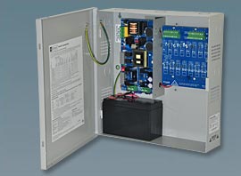
Altronix Eflow16 Low Voltage Power SupplyWe’ve all had it happen: either a bad battery or a blown fuse in a security power supply.   It causes cameras to fail, a card access door to stop working, or a whole panel to fail.

Power supplies in their simplest sense do a very basic thing:  They turn 120 volts AC power to low voltage DC power for low voltage security devices such as cameras, card readers, alarm panels, or detection devices.   And while they have become more sophisticated, adding fused outputs, relay contacts for fire alarm disconnects (life safety egress for maglocks), and smart battery chargers, until recently it was up to the security integrator or maintenance staff to maintain the power supply by testing power and replacing batteries periodically.

In the IT world, just about everything is monitored – Computer servers, network switches, server room air conditioning and filtration units, UPS battery backup systems, even cameras in the data closet monitoring temperature, humidity, and noise levels.  Much of this information is sent via the Simple Network Management Protocol (SNMP).  This protocol is monitored by software that notifies console operations of the exact conditions or problems that may arise with hardware or software in the footprint.

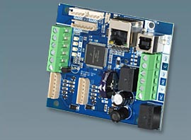
Enter the power supply network module.  The Altronix LINQ2 is a new product that offers the same kind of monitoring capability used in the computer industry.

The Altronix LINQ2 network module is designed to interface with eFlow and MaximalF power supply/chargers. It enables power supply status monitoring and control of two (2) eFlow power supply/chargers over a LAN/WAN or USB connection. LINQ2 provides values on demand for AC fault status, DC current and voltage, as well as Battery fault status and reports conditions via SNMP.

Now security operations can be notified of potential problems and critical failures as they happen, or maybe even before.

For more information visit http://www.altronix.com/products/product.php?name=LINQ2

Altronix linq2 SNMP module

The Altronix LINQ2 SNMP Network Module

Posted in: Fire and Life Safety, New Equipment and Gadgets, Security Technology

Leave a Comment (0) →

Layers – Not just for Onions and Ogres

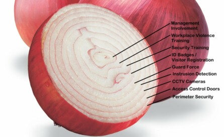
Security has been thought of and taught to others as a “layered approach” for centuries, and as such is not a new concept.   The Romans used layered concepts in their infantry tactics as well as their defensive fortifications.   With all due respect to “Shrek“, security is like an onion, and is a complex layer of countermeasures that make up a suite of hurdles that, presumably, are so confounding or problematic that the opponent gives up, gets caught, or never attempts anything in the first place.

The layers of security

Layers of security are a simple concept, but the concept is often overused by security professionals in discussion and even trivialized as not very important.  As Americans, we tend to rely very heavily on technology.  We understand technology, and we’re pretty good at it.   But while having thermal night vision cameras, fiber optic sensing cables, and CCTV drones flying over your campus are an impressive security posture, sometimes just a plain old chain link fence or dense thornbush hedge are enough to deter the would be criminal.  The most effective barrier I ever saw was a dense hedge of thorns called a  “living wall”.   It was 6 feet tall (and still growing), and you couldn’t climb it, cut it, or burn through it.

We once worked with a client that had installed a $4500.00 bullet proof door with a card access proximity reader installed behind Lexan (to protect it too) on the wall.  It we very impressive, until we learned that the wall it was installed  in was only sheetrock and metal studs, and you could kick through it and completely bypass the door.

Security layers mean from the outside in, with each layer adding to the increased security profile.   But security profiles are different for different companies, buildings, or campuses.  It depends upon the corporate philosophy, culture, and threat profile.  What may be reasonable for a chemical company manufacturing DOD explosives may not be suitable for a quarry.

Start with the outside, what are the threats from the street, the site perimeter, or even from the air?  Then work to the building perimeter, where are points of entry, access control weaknesses, or blind spots?  Internally you should look at the lobbies, common areas, break rooms, stairwells, and vestibules.  Then finally to policies and procedures relating to security, safety, and employee awareness.  Each of these areas will generate questions, to which you should generate answers in the forms of layers of security to add to your security profile.

Posted in: CPTED, Security Consulting

Leave a Comment (0) →
Page 1 of 2 12